|
|
|
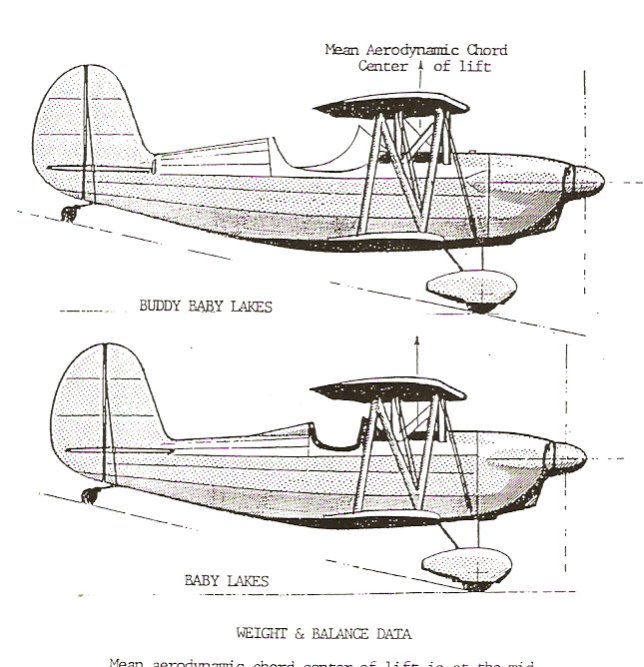
WEIGHT AND BALANCE DATA
Mean aerodynamic cord (MAC) center of lift is at the midpoint between the forward and aft attach points of the cabane struts.
Ideal loaded center of gravity is 0 inch to 1 inch forward of the MAC center of lift.
Loaded center of gravity limits are 4 inches forward to 3 inches aft of the MAC center of lift.
Baby Lakes and Buddy Baby Lakes
MAC (Center of Lift)
NOTES
The airfoil section is a modified M-6 for all except the last 18 inches of span where it transitions to a USA-15 on both upper and lower wing tips.
Stagger between upper and lower wings is approximately 30% of the cord at the root becoming nil at the tips du to the upper wing sweep-back.
The upper wing is set a 1 degree more angle of incidence (2 ½ degrees) than the lower wing (1 ½ degree).
There should be no dihedral in the lower wing and from 0 degrees to 2 degrees dihedral in the upper wing.
Flight testing has shown that the lift (pressure) profile resulting from this wing configuration produces the following results:
a) In cruise
level flight at about 115-120 MPH, with a gross weight
of 800 pounds, all lift is bring generated by the
upper wing with the lower wing
being essentially streamlined with the relative wind.
b) In condition a) above, the
mean aerodynamic cord center of lift
is at midpoint between
the forward and aft cabane
attachments for the upper wing.
c)
As the angle of attack
(for both wings) is increased, the lower wing begins to generate
lift aft of the upper wing
center of lift. The combination
of both upper and lower
lift profiles has the overall effect of maintaining a
combined
center of lift that
remains almost constant relative
to the center of gravity at all angles of attack right
up through
full stall of the upper wing.
d)
As the upper wing stalls,
the center of lift is then (initially) well aft
of position described in b) above (midpoint
between forward and aft
cabane attach points) which causes an immediate pitch down
of the aircraft's attitude.
The ideal loading (pilot, fuel, oil, etc) center of gravity is from 0 inch to 1 inch forward of the midpoint between upper wing cabane forward and aft attach points.
Loaded center of gravity limits should be held to from 4 inches forward to 3 inches aft of the midpoint of the cabane attached points. (Even through the aircraft has been found to be controllable when the center of gravity was well outside these limits.)
Before fabrication the engine mount for a Baby Lakes or Buddy Baby Lakes, a calculation should be made to determine how far forward of the MAC center of lift (for the upper wing) will the engine, cowl, prop, wheel pants, etc have to be in order to provide a plus moment that is about equal to the minus moment of (intended) pilot (and passenger in the Buddy Baby).
It is important to use the cabane struts attachment mid point as the primary reference for weight and balance calculations since firewall (the usual datum) position and seat back position are often adjusted to accommodate pilot size and comfort considerations (see sheets on weight and balance)
Loaded Gross Weight vs Structural G Limits
850 pounds max. for 9 G positive and negative.
1000 pounds max for 7.5 G positive and negative
The Baby's C.G. range is sufficient to allow for a difference in
pilot weights as much as 40-50 pounds either side of the 170 pound if its initial balance falls at the C.L. of M.A.C. With a
170 pound pilot. However, its overall performance is
proportionally less as you approach the extremes of the C.G. range.
ADDITIONAL NOTES
See some comparable weights and approximated C.G.'s for different engines in the table below. Differences in same models occur with different dash numbers and all are given with accessories except starter and generator.
MAKE MODEL WEIGHTS ENGINE C.G.
Continental A-65 163
lbs 6.2
inches
C-75
177-182
lbs. 6.2 - 4.6 inches
A-80
173-176
lbs. 6.2
inches
C-85
178-180
lbs. 6.2
- 4.6 inches
C-90-8
184
lbs. 6.2
inches
C-90-F
188
lbs
4.6 inches
0-200
190
lbs
4.6 inches
Lycoming
0-235
209-219 lbs. 7 inches
Lycoming
0-290
230-250
7 inches
C.G. measurements are taken forward of the rear face of engine mounting pads. Adaption of some of the heavier engines might require moving pilot aft or weighting the tail.
For horsepower rating above 90 HP
the engine mount should be made to give up to 3 degrees
down thrust
to the prop
shaft. (one way is to install a 1 inch spacer at top mounting
points
only). This improves the climb rates and also improves the take-off
characteristics. Leave it to 0 degrees (standard) if you are going
to fly it inverted for extended periods.
For an aircraft that is to be used for extensive inverted flying, the incidence of the lower wing should be reduced to 0 degrees with the top wing at 1 degree. This will give a more level fuselage attitude in both modes. Actually, within reason (1-3 degrees) the exact incidence, relative to the longitudinal axis, is not too important as long as the relationship of 1 degree more on top wing than the bottom wing is maintained. Basic incidence merely establishes fuselage attitude in flight.
Have a great day!
Harvey Swack
to go back, click on link below